|


|
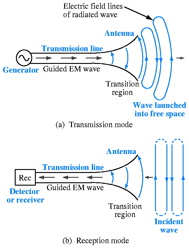
Figure 9.1: |
Antenna as a transducer between a guided electromagnetic
wave and a free-space wave, for both transmission and reception.
|
|
|
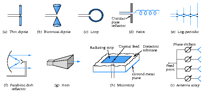
Figure 9.2: | Various types of antennas.
|
|
|
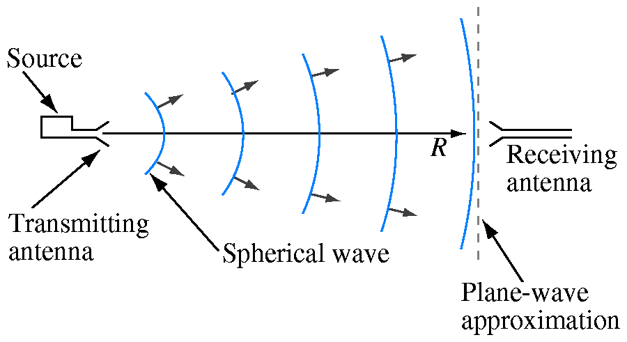
Figure 9.3: | Far-field plane-wave approximation.
|
|
|
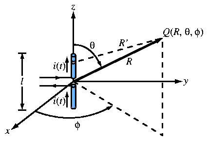
Figure 9.4: | Short dipole placed at the origin of a spherical
coordinate system.
|
|
|
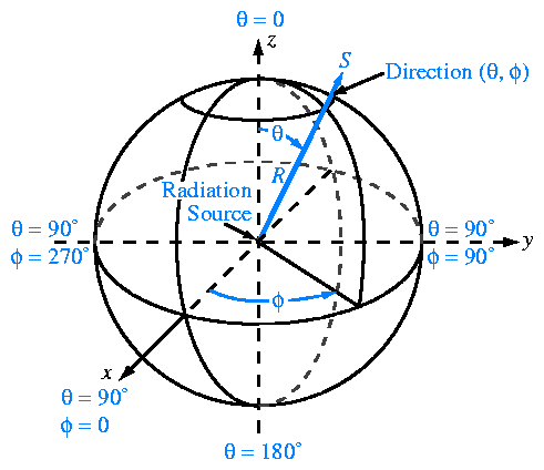
Figure 9.5: | Spherical coordinate system.
|
|
|
Figure 9.6: | Electric field lines surrounding an oscillating dipole at
a given instant.
|
|
|
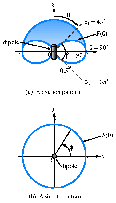
Figure 9.7: | Radiation patterns of a short dipole.
|
|
|
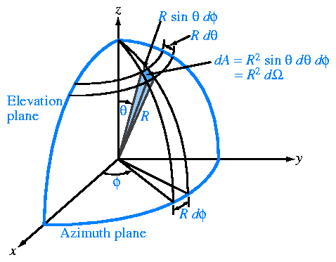
Figure 9.8: |
Definition of solid angle d = sin = sin  d
d d
d . .
|
|
|
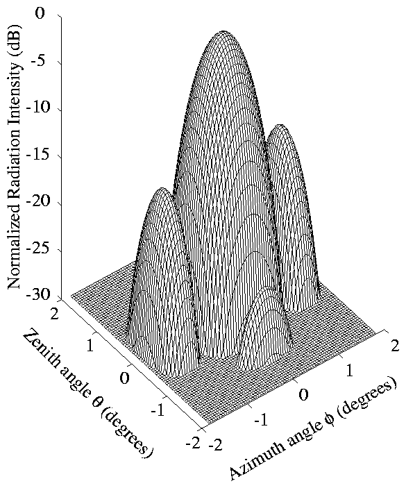
Figure 9.9: |
Three-dimensional pattern of a narrow-beam antenna.
|
|
|
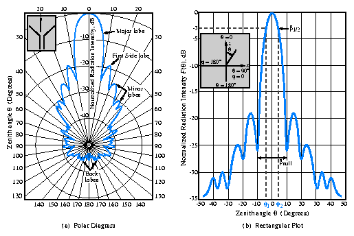
Figure 9.10: | Representative plots of the normalized radiation pattern
of a microwave antenna in (a) polar form and (b) rectangular form.
|
|
|
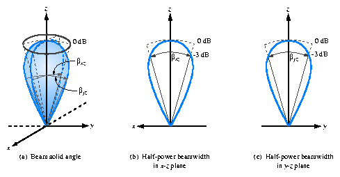
Figure 9.11: |
The pattern solid angle p defines an equivalent
cone over which all the radiation of the actual antenna is concentrated
with equal intensity equal to the maximum of the actual pattern.
|
|
|
Figure 9.12: |
The solid angle of a unidirectional radiation pattern is
approximately equal to the product of the half-power beamwidths in the
two principal planes; that is,
p =
 xz
yz. xz
yz.
|
|
|
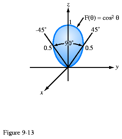
Figure 9.13: |
Polar plot of F()= cos2 .
|
|
|
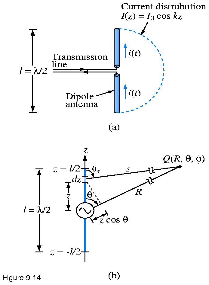
Figure 9.14: | Center-fed half-wave dipole.
|
|
|
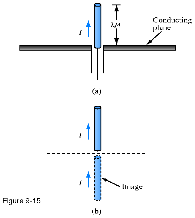
Figure 9.15: | A quarter-wave monopole above a conducting plane is
equivalent to a full half-wave dipole in free space.
|
|
|
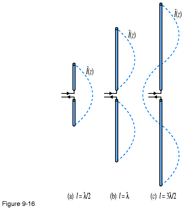
Figure 9.16: | Current distribution for three center-fed dipoles.
|
|
|
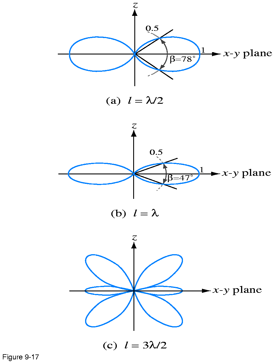
Figure 9.17: |
Radiation patterns of dipoles with lengths of
 /2,
,
and 3/2. /2,
,
and 3/2.
|
|
|
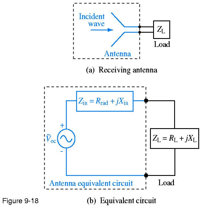
Figure 9.18: | Receiving antenna represented by an equivalent circuit.
|
|
|
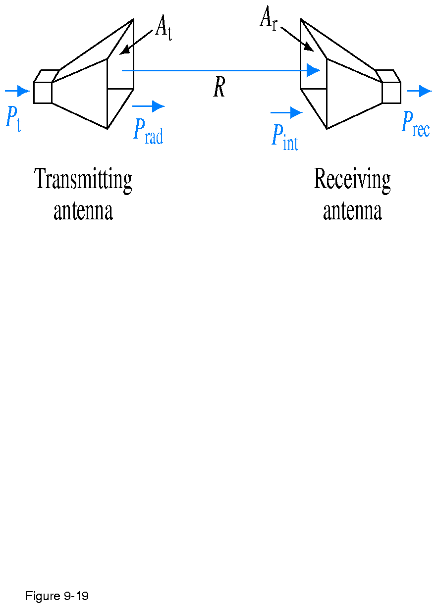
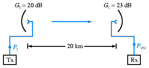
Figure 9.19: | Transmitter-receiver configuration.
|
|
|
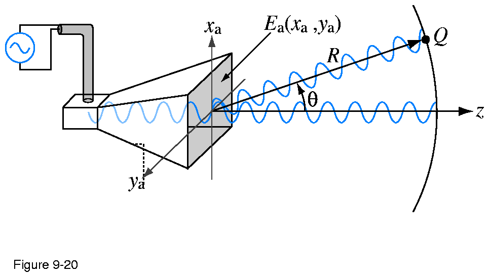
Figure 9.20: |
A horn antenna with aperture field distribution Ea(xa,
ya).
|
|
|
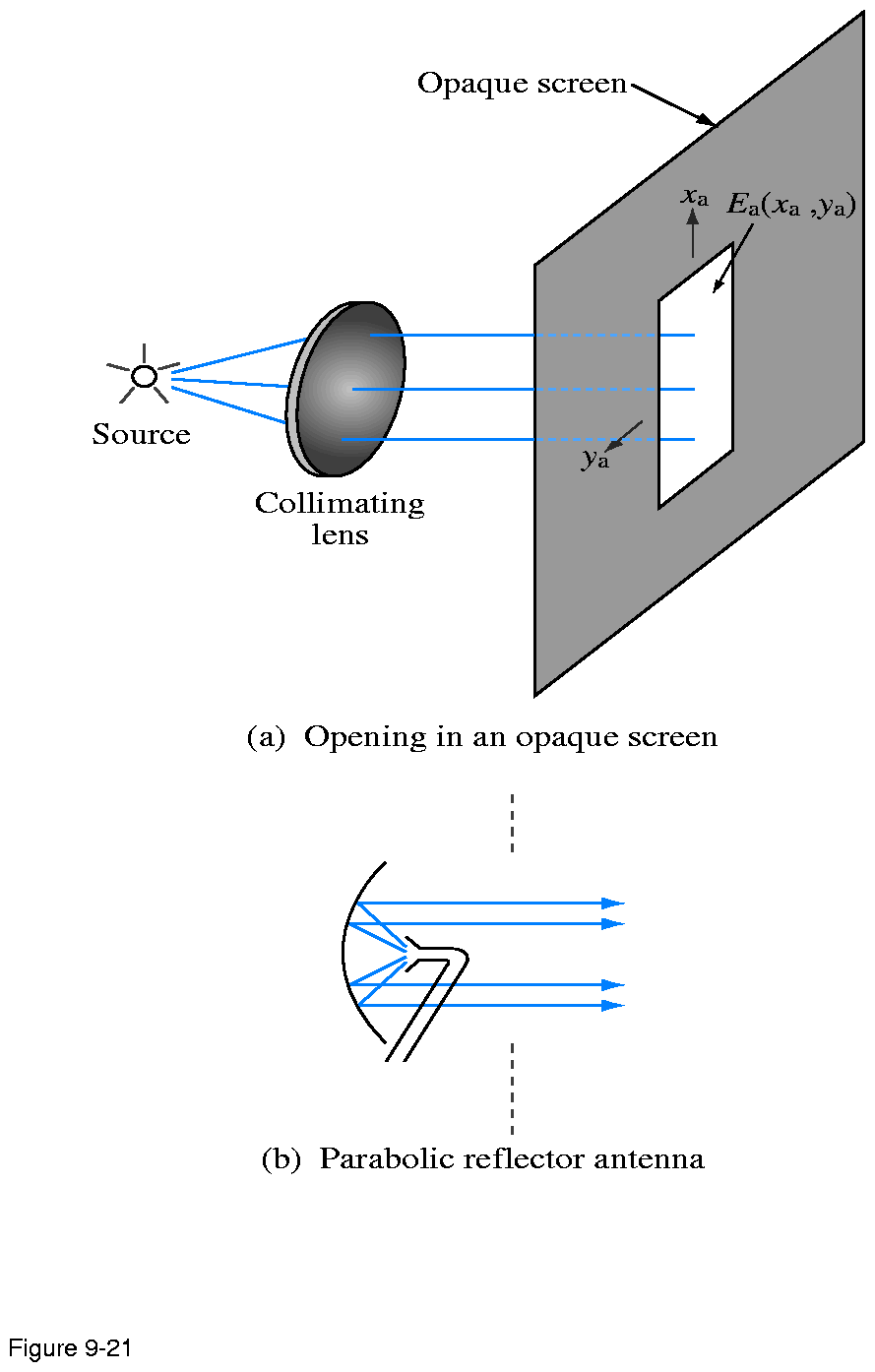
Figure 9.21: |
Radiation by apertures: (a) an opening in an opaque
screen illuminated by a light source through a collimating lens and (b)
a parabolic dish reflector illuminated by a small horn antenna.
|
|
|
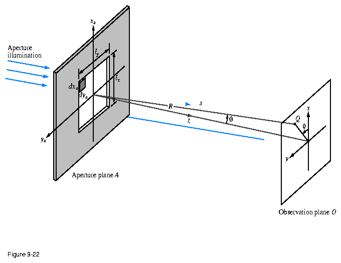
Figure 9.22: |
Radiation by an aperture in the xa-ya plane at z=0.
|
|
|
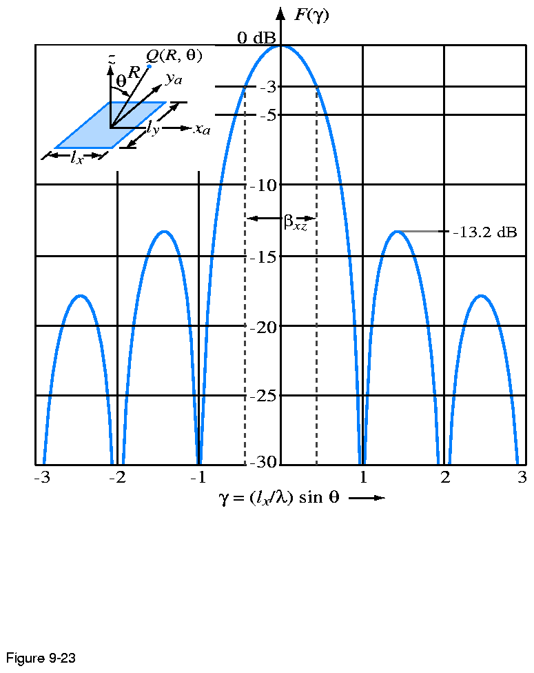
Figure 9.23: |
Normalized radiation pattern of a uniformly illuminated
rectangular aperture in the x-z plane (= 0).
|
|
|
Figure 9.24: |
Radiation patterns of (a) a circular reflector and (b) a
cylindrical reflector (side lobes not shown).
|
|
|
Figure 9.25: |
The AN/FPS-85 Phased Array Radar Facility in the Florida
panhandle, near the city of Freeport. A several-mile no-fly zone
surrounds the radar installation as a safety concern for
electroexplosive devices, such as ejection seats and munitions, carried
on military aircraft.
|
|
|
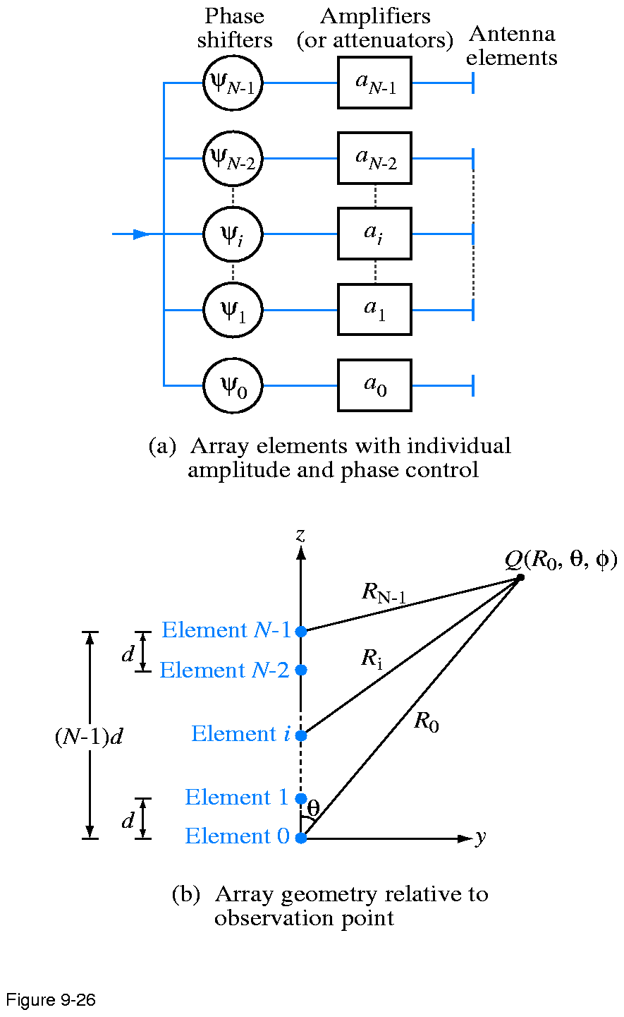
Figure 9.26: |
Linear-array configuration and geometry.
|
|
|
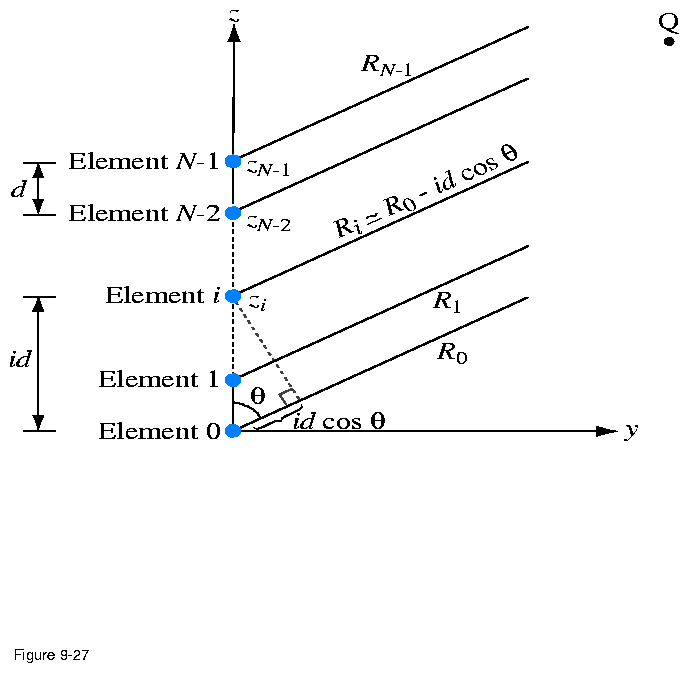
Figure 9.27: |
The rays between the elements and a faraway observation
point are approximately parallel lines. Hence, the distance Ri
=R0 - id cos .
|
|
|
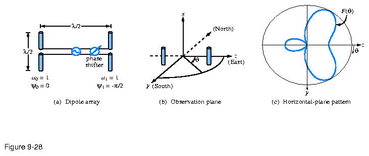
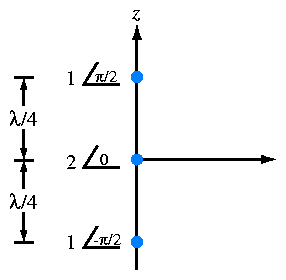
Figure 9.28: | Two half-wave dipole array of Example 9-6.
|
|
|
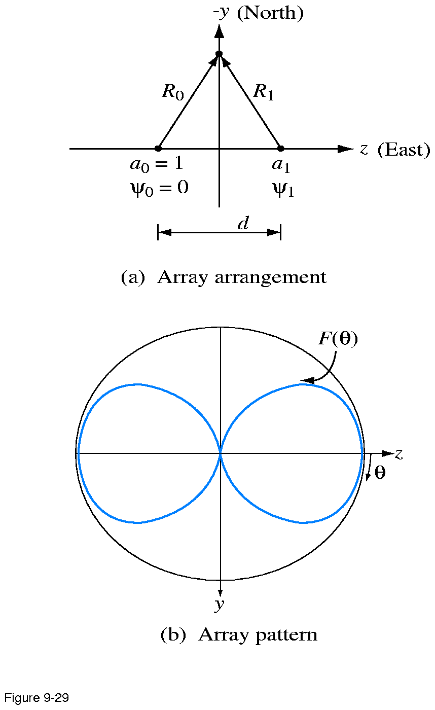
Figure 9.29: |
(a) Two vertical dipoles separated by a distance d along
the z-axis; (b) normalized array pattern in the y-z plane for a0= a1=
1,  1= 0=
- 1= 0=
- , and d=/2. , and d=/2.
|
|
|
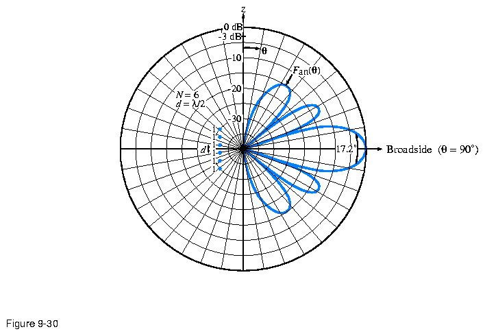
Figure 9.30: |
Normalized array pattern of a uniformly excited
six-element array with interelement space d= /2.
|
|
|
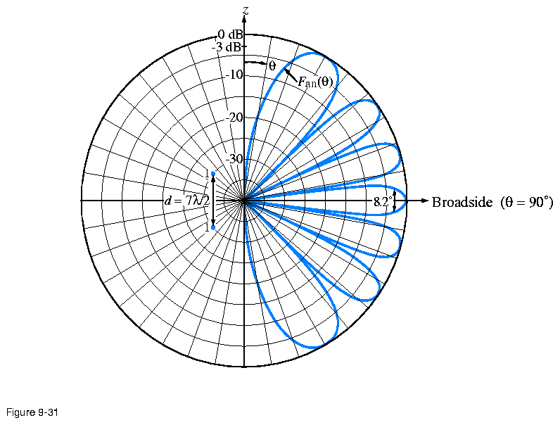
Figure 9.31: |
Normalized array pattern of a two-element array with
spacing d=7/2.
|
|
|
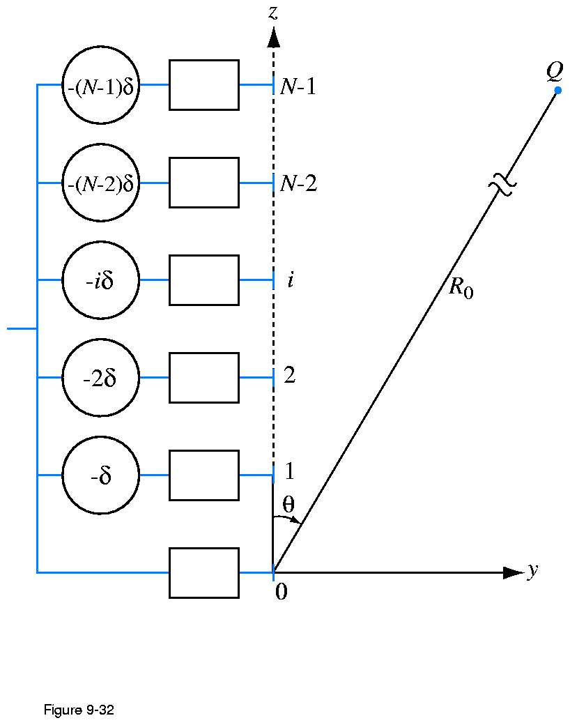
Figure 9.32: | The application of linear phase.
|
|
|
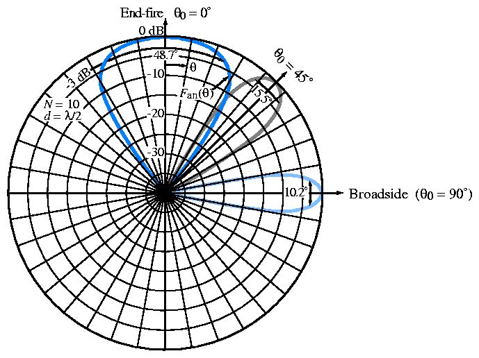
Figure 9.33: |
Normalized array pattern of a 10-element array with
/2 spacing between adjacent elements.
|
|
|
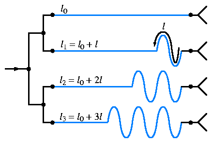
Figure 9.34: |
An example of a feeding arrangement for frequency-scanned arrays.
|
|
|
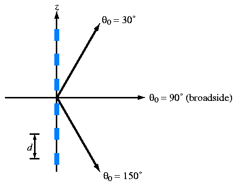
Figure 9.35: | Steerable six-element array (Example 9-9).
|
|
|
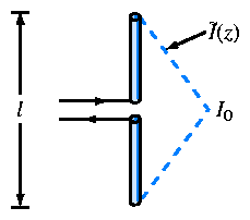
Figure 9.36: | Triangular current distribution on a short dipole
(Problem 9.13).
|
|
|
Figure 9.37: | Communication system of Problem 9.22.
|
|
|
Figure 9.38: | Three-element array of Problem 9.34.
|